Imagine you nailed everything from Part 1. The camera is perfect, the lens is framed beautifully, the lighting is kind, and there are plenty of pixels on every target. You open the live view, lean back, and the footage stutters, freezes, smears into blocky mush, then drops out entirely. The camera is innocent. The problem is the part nobody photographs for the brochure: the network underneath it.
Welcome back to the Intelligent Video Analytics series. In the last episode we ended on a promise: once you have great pixels, you still have to get them to the analytics without choking the network or leaving the door open. That is the entire job of today’s article. We are going to follow the video off the camera and into the wires.
Remember the capture-to-storage chain we drew last time? Scene, lens, sensor, processor, transmission, recorder, analytics. Part 1 lived in the first few links. Today we live in two unglamorous but decisive ones: transmission (getting the video across the network) and recorder (storing it). Get these wrong and it does not matter how good your camera was; you are back to feeding analytics garbage, just by a different route.
A camera feed is a data stream you have to plan for#
Here is the mental shift that makes everything else click. A modern IP camera is not really sending you “video.” It is sending you a continuous stream of data, measured in megabits per second (Mbps), and that stream has to share a finite network with every other camera and, often, with the regular office traffic too.
Raw, uncompressed video is enormous, comically so. A single uncompressed 1080p stream at 30 frames per second would run into the gigabits per second. No sane network carries that. So cameras compress aggressively before the data ever hits the wire, which is why compression is going to be the single biggest lever we pull later. But even compressed, the numbers add up fast, because surveillance has a brutal multiplier: many cameras, recording all day, every day. One camera is a trickle. Two hundred cameras running 24/7 is a river, and rivers need real channels.
So the first principle of network design for video is simply this: treat the feed as a data budget, not an afterthought. An under-provisioned network does not fail politely. It loses frames, delays the live view, and silently drops the resolution right when you need detail most. Let’s build that budget properly. But first, the shape of the network itself.
Topologies: the shape of the network#
A network topology is just the pattern in which you wire devices together. There are five common ones, and each is a trade between cost, scalability, and how gracefully the system survives a failure. Each maps neatly onto a real-world site, so let’s use those.
A star topology connects every camera back to one central point, usually a switch or recorder. It is simple, cheap, and easy to troubleshoot, which is why a small retail store with each camera wired to a central DVR (Digital Video Recorder) is the textbook case. The weakness is obvious: the center is a single point of failure. If the hub dies, everyone dies with it.
A ring topology connects each device to two neighbors, forming a loop. Because traffic can travel either way around the ring, a single broken cable does not take the system down. A multi-level parking garage that needs continuous coverage on every floor is a good fit.
A bus topology strings devices along a single shared backbone cable. It is cheap and quick to lay down, which makes it handy for a temporary deployment like a music festival, but the shared line becomes a bottleneck and a liability as you add cameras.
A mesh topology connects devices to multiple others, so there are many possible paths between any two points. This is the most resilient and the most expensive, the choice for a high-security facility like a data center where downtime is simply not acceptable.
A hybrid topology mixes these, which is what most real, larger sites actually use. A corporate campus might run a star inside each building and link the buildings with a ring or bus backbone. You get local simplicity and site-wide resilience.
flowchart TD
    subgraph Star["Star · retail store"]
        H((Switch)) --- C1[Cam]
        H --- C2[Cam]
        H --- C3[Cam]
    end
    subgraph Mesh["Mesh · data center"]
        M1[Cam] --- M2[Cam]
        M2 --- M3[Cam]
        M3 --- M1
    end
The two ends of the spectrum: the simple star and the resilient mesh. Ring, bus, and hybrid sit in between.
The honest takeaway: you do not pick a topology because it is fashionable, you pick it by matching the site’s size, budget, and tolerance for downtime. Small and simple? Star. Cannot ever go dark? Mesh. Lots of buildings? Hybrid.
Bandwidth math: the part teams skip and regret#
Now the math everyone wishes they could avoid and nobody should. The good news: the core formula is almost insultingly simple.
Note
Total bandwidth (Mbps) = bitrate per camera (Mbps) x number of cameras
That is it. The complexity is not in the formula, it is in the inputs, because the bitrate per camera depends on resolution, frame rate, compression codec, and how busy the scene is. A static storage room compresses down to almost nothing; a windy car park full of moving trees and headlights does not.
Let’s do a real worked example, the kind you would actually present to a client.
Say you are designing for 40 cameras, each streaming at 3 Mbps (a reasonable figure for 1080p at a moderate frame rate on H.264). Multiply it out:
3 Mbps x 40 cameras = 120 Mbps (baseline)But you never design to the baseline, because peak moments and future cameras exist. The rule of thumb is to add 20 to 30 percent headroom. Take 25 percent:
120 Mbps + (0.25 x 120) = 150 Mbps totalSo a 40-camera system needs roughly 150 Mbps of provisioned bandwidth, not 120. That headroom is not padding for its own sake; it is what keeps the live view smooth during a busy incident, exactly when you cannot afford stutter.
The same logic scales. A regional airport planning 48 cameras at 2.5 Mbps each with 25 percent headroom lands at almost the same number, about 150 Mbps per backbone segment, sized so the command center can watch live feeds during peak hours without starving the recorders. Notice how two different camera counts can need similar bandwidth: the per-camera bitrate matters as much as the count. Which brings us to the most powerful dial on the whole board.
Compression and bitrate: the lever that halves your bill#
If bandwidth math tells you how big the river is, compression decides how much water you actually have to move. Choosing the right codec and bitrate strategy is the highest-leverage decision in the entire network design.
On codecs, three names come up:
H.264 (AVC) is the widely supported workhorse, good quality at moderate compression, and a safe default for compatibility. H.265 (HEVC) is the upgrade: it delivers the same visual quality at up to 50 percent lower bitrate, which is why it is the go-to for 4K and storage-constrained sites. The catch is that it costs more processing power to encode and decode, so very old hardware may struggle. MJPEG compresses each frame independently, giving high per-frame quality but eating enormous bandwidth and storage, so it is rarely used for continuous recording today.
Then there is how the codec spends its bits, the bitrate control strategy:
Constant Bit Rate (CBR) holds a fixed bitrate no matter what is happening on screen. It makes storage trivially predictable, but it wastes bandwidth on empty, static scenes, paying full price to record an empty hallway. Variable Bit Rate (VBR) adapts to the scene, spending fewer bits when nothing moves and more when something does. It is more efficient but its load is, by definition, variable and harder to plan. Smart codec features (vendor names for content-adaptive encoding) push this further with tricks like region-of-interest encoding and background suppression, spending bits on the moving person and almost nothing on the static wall behind them.
How much does this actually save? Concretely: a 1080p camera on H.264 at 15 fps might need about 3 Mbps. The same feed on H.265 could need only 1.5 to 2 Mbps. Now multiply that across a fleet. A logistics warehouse with 60 full-HD cameras that switched from H.264 to H.265 and turned on smart encoding cut bandwidth usage by about 45 percent. That saving was enough to cancel a planned switch upgrade and redirect the money toward analytics hardware instead. That is the whole game: compression is where good network design quietly pays for the AI you actually wanted to build.
Tip
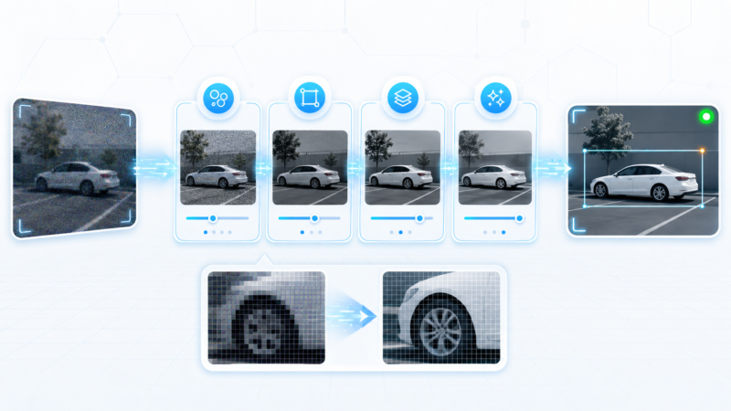
There is an analytics caveat here, and it ties straight back to Part 1. Compression is lossy, and crank it too hard and you destroy the very detail your analytics needs. An over-compressed license plate is unreadable to a model just as surely as a blurry one. Compress to save money, but never below the quality your detection task requires. Pixels on target, again.
The hardware that actually moves the video#
Topologies and bitrates are abstractions until real boxes carry the traffic. A few you should know by name.
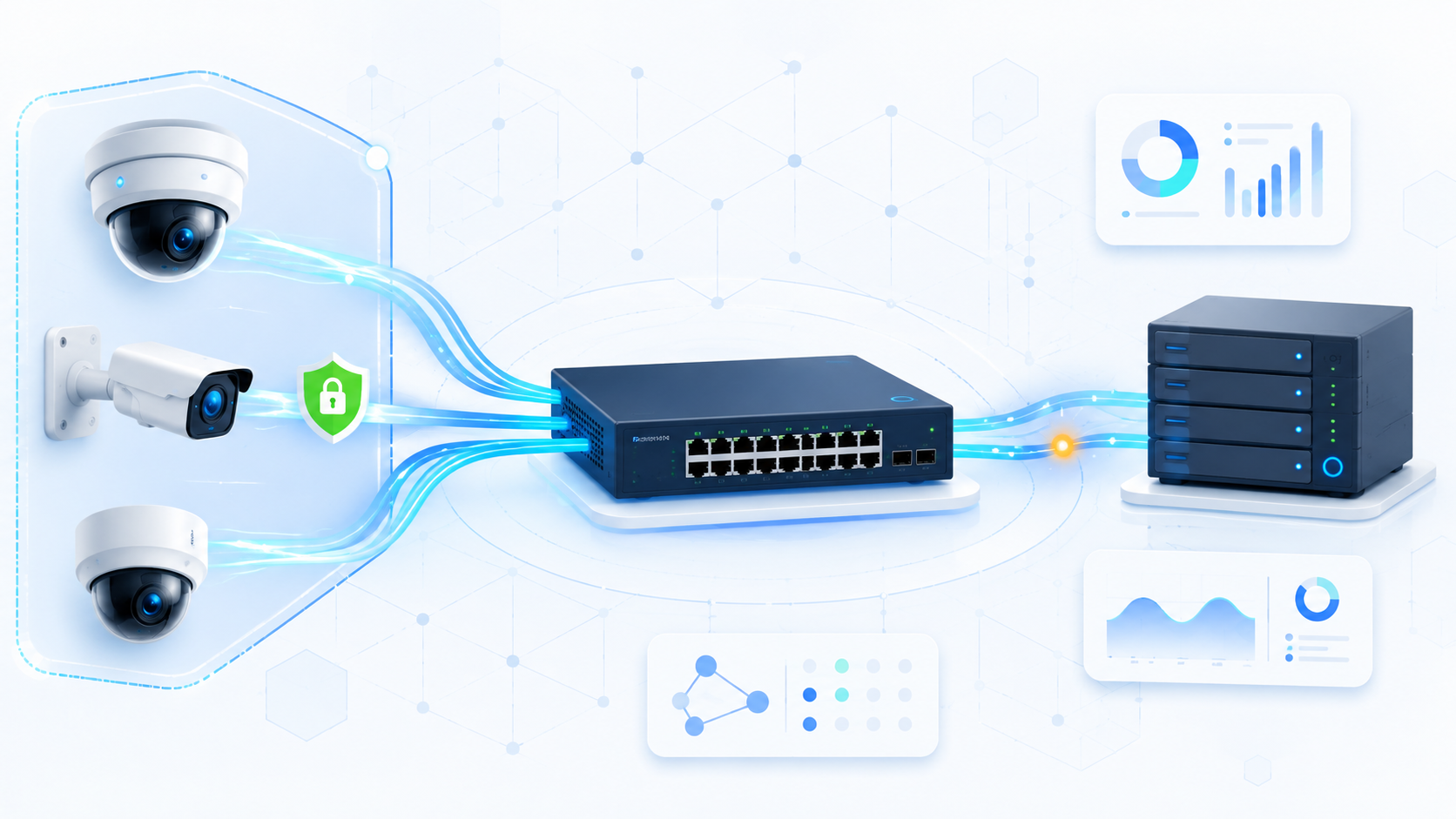
Managed switches are the backbone. Unlike a dumb home switch, a managed switch supports features that surveillance leans on heavily: VLANs (we will get to those in a second), QoS (Quality of Service) for prioritizing video, and per-port controls. Many access switches also provide Power over Ethernet (PoE), which we met last episode: power and data down one cable. The detail to plan for is the switch’s PoE power budget, the total wattage it can deliver across all ports. Load it with hungry PTZ or heated outdoor cameras and a cheap switch will run out of power long before it runs out of ports.
Routers connect your camera network to other networks and often add firewall and VPN features for secure remote access. The NVR (Network Video Recorder) stores the IP camera feeds, as we covered in Part 1.
Sitting on top of the hardware is the VMS (Video Management Software), the application operators actually live in for monitoring, recording, playback, and increasingly analytics. It is worth knowing the commercial landscape, because in the real world you will be specifying or integrating with these. Three names dominate. Genetec Security Center is a unified platform that combines live monitoring, recording, and analytics, scales to very large deployments, and puts heavy emphasis on cybersecurity and privacy with built-in encryption. Milestone XProtect is known for its modular, open approach and huge ecosystem of third-party integrations, scaling from a handful of cameras to complex multi-site systems. Avigilon Control Center (ACC) stands out for AI-driven analytics built in, with real-time event detection, facial recognition, and license plate recognition, wrapped in a user-friendly interface. You do not need to memorize feature lists; you do need to know these exist and that the VMS is where your analytics will surface to a human.
Your cameras are a target: security that matters#
Time for the uncomfortable part. A camera on your network is a small, often poorly secured computer, frequently shipped with a default password that half the internet already knows. An attacker who compromises one camera may be able to use it as a foothold into the rest of your network. The surveillance system you installed to improve security can, if you are careless, become the weakest link in it. So treat the network as defended infrastructure, not just plumbing.
The defenses stack in layers:
Network segmentation is the big one. Using VLANs (Virtual Local Area Networks), you put the cameras on their own logical network, separated from office PCs and servers. If a camera is compromised, the damage is contained to the camera segment instead of spreading to payroll. Segmentation also reduces congestion and makes the whole thing easier to monitor.
Encryption scrambles the video in transit so that even if someone taps the wire, they get noise instead of footage. Access control means strong, unique credentials and role-based permissions, so not everyone who can view cameras can also delete recordings, and absolutely nobody is still running the factory default password. Firewalls filter what traffic is allowed in and out of the camera network. Intrusion Detection and Prevention Systems (IDPS) watch for suspicious patterns and can block them automatically. Regular software updates and patches close the known holes that attackers specifically hunt for. And physical security still counts: a camera you can unplug or a recorder anyone can walk off with is not secure, however good the software is.
flowchart LR
    subgraph Cameras["Camera VLAN (isolated)"]
        K1[Cam] --- SW[Managed switch]
        K2[Cam] --- SW
    end
    SW --> FW[Firewall + IDPS]
    FW --> REC[NVR / VMS server]
    FW -. blocks .-> OFF[Office LAN]
None of this is exotic. It is the difference between a system that protects the building and one that quietly endangers it.
Architecture best practices: building it to last#
Beyond basic connectivity, professional-grade deployments are intentionally architected. A few patterns separate the systems that age gracefully from the ones that collapse the first time something breaks.
Layered design. Group cameras into logical tiers rather than one flat soup: by function (perimeter, indoor, license plate recognition each have different priorities), by area (lobbies, parking, executive floors isolated into their own VLANs for traffic and privacy control), and by resolution or analytics priority (4K and analytics-heavy cameras grouped so they get dedicated bandwidth without starving standard feeds). This improves scalability, fault isolation, and your sanity when troubleshooting.
Redundancy and high availability. Remove single points of failure. Dual uplinks between switches, managed with STP (Spanning Tree Protocol, which blocks redundant paths until they are needed to prevent loops) or LACP (Link Aggregation Control Protocol, which bundles links so they are all active and share load). Add N+1 core switches and failover recording servers, so one spare can take over instantly when a primary fails. Connect servers with dual network cards, bonded for redundancy and throughput. The goal is simple: a hardware failure should be a non-event, not an outage.
QoS. On a converged network where cameras share infrastructure with regular IT traffic, video needs priority or it will lose the fight with someone’s giant file download. DSCP (Differentiated Services Code Point) tags mark video packets as high priority, VLAN-based policies guarantee bandwidth per camera group, and critical feeds (entrances, cash zones, public intersections) get reserved uplink capacity. A university campus, for example, can guarantee that dorm and parking-structure cameras always beat student Wi-Fi for transmission priority.
NTP (Network Time Protocol). Every device must agree on the time. This sounds trivial until it isn’t. Here is a cautionary tale: investigators reviewing a coordinated theft found one set of cameras was 90 seconds out of sync with the others, which scrambled the event timeline and caused real confusion about what happened when. Synchronizing every camera, switch, and server to a reliable NTP source keeps timestamps consistent, which is essential both for forensic evidence and for any analytics that correlates events across multiple cameras.
Multicast and sub-streaming. Two scaling tricks worth knowing. With ordinary unicast, every operator watching a feed creates a separate copy of the stream, multiplying bandwidth. Multicast sends one stream that many viewers share, which is ideal in a command center, though it needs switch support (IGMP snooping, the mechanism switches use to track which devices have joined a multicast group) to work cleanly. Sub-streaming leans on a feature many IP cameras already have: emitting two or three streams at once, a high-resolution stream for recording and analytics, and a low-resolution sub-stream for mobile apps and live operator views. You archive in 4K while your phone app sips a lightweight feed.
flowchart LR
    CAM[IP camera] --> HI[High-res stream<br/>record + analytics]
    CAM --> LO[Low-res sub-stream<br/>mobile + live view]
    HI --> NVR[NVR / analytics]
    LO --> APP[Operator console / phone]
Putting it together: a smart-city snapshot#
To see all of this cooperating, picture a smart-city command center: 400-plus cameras spread across traffic, public spaces, and buildings. Each district sits in its own VLAN for isolation and policy control. Core switches connect to the recording servers with full mesh uplinks for resilience. Every component synchronizes to a citywide NTP system so timestamps line up across the whole city. And sub-streaming keeps real-time monitoring light while still preserving 4K archives for investigations. Every concept from this article shows up at once: topology, segmentation, redundancy, time sync, and stream optimization, all in service of moving a flood of video reliably and securely.
The “will this network hold up?” checklist#
Mirroring Part 1’s camera checklist, here is the gut-check for the network. If you cannot answer yes to all of these, fix the plumbing before you trust it with analytics.
- Bandwidth budget: have I summed the per-camera bitrates and added 20 to 30 percent headroom, with realistic bitrates for the scenes, not best-case guesses?
- Compression fit: am I using an efficient codec (H.265 where hardware allows) and a bitrate strategy that saves money without crushing the detail analytics needs?
- Topology match: does the network shape fit the site’s size and tolerance for downtime?
- Power budget: does each PoE switch have enough wattage for all the cameras it powers, with headroom?
- Segmentation: are cameras on their own VLAN, isolated from the office network and behind a firewall?
- Security hygiene: default passwords changed, encryption on, patches current, access roles defined?
- Resilience: redundant uplinks, N+1 or failover for the critical switches and recorders?
- Time sync: is every device on a common NTP source so timestamps agree?
Wrapping up#
The network is the part nobody puts on the brochure, and it is the part that quietly decides whether your beautiful pixels ever arrive intact. We sized a real bandwidth budget, watched compression cut a fleet’s costs by nearly half, isolated the cameras so one weak device cannot sink the whole building, and built in the redundancy and time sync that separate a professional system from a fragile one.
The short version, if you forget everything else: a camera feed is a data budget you must plan, compress wisely, and defend, because an unplanned or unprotected network is just another way to feed analytics garbage.
Next up, we finally start turning pixels into meaning. Episode 3 is about image processing for video analytics: enhancement, low-light, compression artifacts, and the detection and segmentation steps that sit just below the AI. The pixels have arrived; now we make them useful. See you there.