Here’s a fact worth sitting with for a second: a bolt of lightning and the processor in your phone are made of exactly the same thing. Charge, current, voltage; everything we built up in Part 1. One of them vaporizes trees. The other one runs a spreadsheet.
The difference isn’t the electricity. The difference is control.
A lightning bolt is current with nothing in its way: billions of coulombs’ worth of push finding the fastest path to ground, all at once. Your phone is the opposite: billions of tiny currents, each one steered, throttled, and metered through paths designed down to the atom. Electronics, as a discipline, is essentially the art of never letting current do what it wants.

The same physics, two outcomes. What separates a lightning strike from a processor is the ability to oppose and meter the flow: resistance.
So this part is about the control knob. It has two halves: resistance, the property that opposes current, and Ohm’s Law, the beautifully simple rule that makes that opposition predictable. By the end you’ll do what every electronics person considers the “hello world” of the field: pick the right resistor to light an LED without frying it. With real numbers, not vibes.
First, let’s pick up the thread we left dangling.
The narrow pipe#
In Part 1 we built the water analogy: voltage is the pressure from the water tower, current is the flow rate through the pipe, and charge is the water itself. And we ended on a teaser: even a tall tower can only push a trickle through a narrow pipe.
That narrowness is resistance. It’s the third character in the story, and it’s the one that makes design possible. A pipe’s width decides how much flow a given pressure produces; a circuit’s resistance decides how much current a given voltage produces. Same idea, same math, one law.
But before the law, let’s look at what resistance physically is.
Resistance: friction for electrons#
Send current through any real material (superconductors excepted) and the charge carriers don’t glide through unbothered. As the free electrons drift, they keep colliding with the atoms of the material’s lattice. Every collision robs a little energy from the electron and hands it to the lattice as vibration, which is to say, as heat.
That opposition is resistance, symbol R, measured in ohms (Ω), named after Georg Ohm, whom we’ll meet properly in a moment. Two things are worth internalizing right away:
- Resistance is where electrical energy leaves the circuit. A resistor is a device for converting electrical energy into heat, on purpose and in a controlled amount. (How much heat a real part can survive is a Part 3 question.)
- Resistance isn’t a defect. It’s the mechanism of control. A circuit with no resistance anywhere isn’t a clean circuit; it’s a short circuit, and it behaves like the lightning bolt.
Geometry sets it#
How much resistance does a chunk of material have? For a uniform piece, three things decide it:
R = ρ · L / A- ρ (rho) is the resistivity: an intrinsic property of the material, in Ω·m. Copper is superb: about 1.7 × 10⁻⁸ Ω·m.
- L is the length. Longer path, more collisions, more resistance.
- A is the cross-sectional area. Thicker conductor, more parallel room for electrons, less resistance.
The water analogy holds perfectly: a long, skinny pipe fights the flow; a short, fat one barely notices it.
Worked example. Take a copper wire 10 meters long with a cross-section of 1.0 mm² (that’s 1 × 10⁻⁶ m², a typical hookup wire):
R = (1.7×10⁻⁸ Ω·m × 10 m) / (1×10⁻⁶ m²) = 0.17 ΩLess than a fifth of an ohm across ten whole meters. That’s exactly what you want from a wire: so little resistance that it’s practically invisible to the circuit. And it’s why power cables are fat and short where currents are large, while a light bulb’s filament, deliberately long and hair-thin, resists so hard it glows white hot.
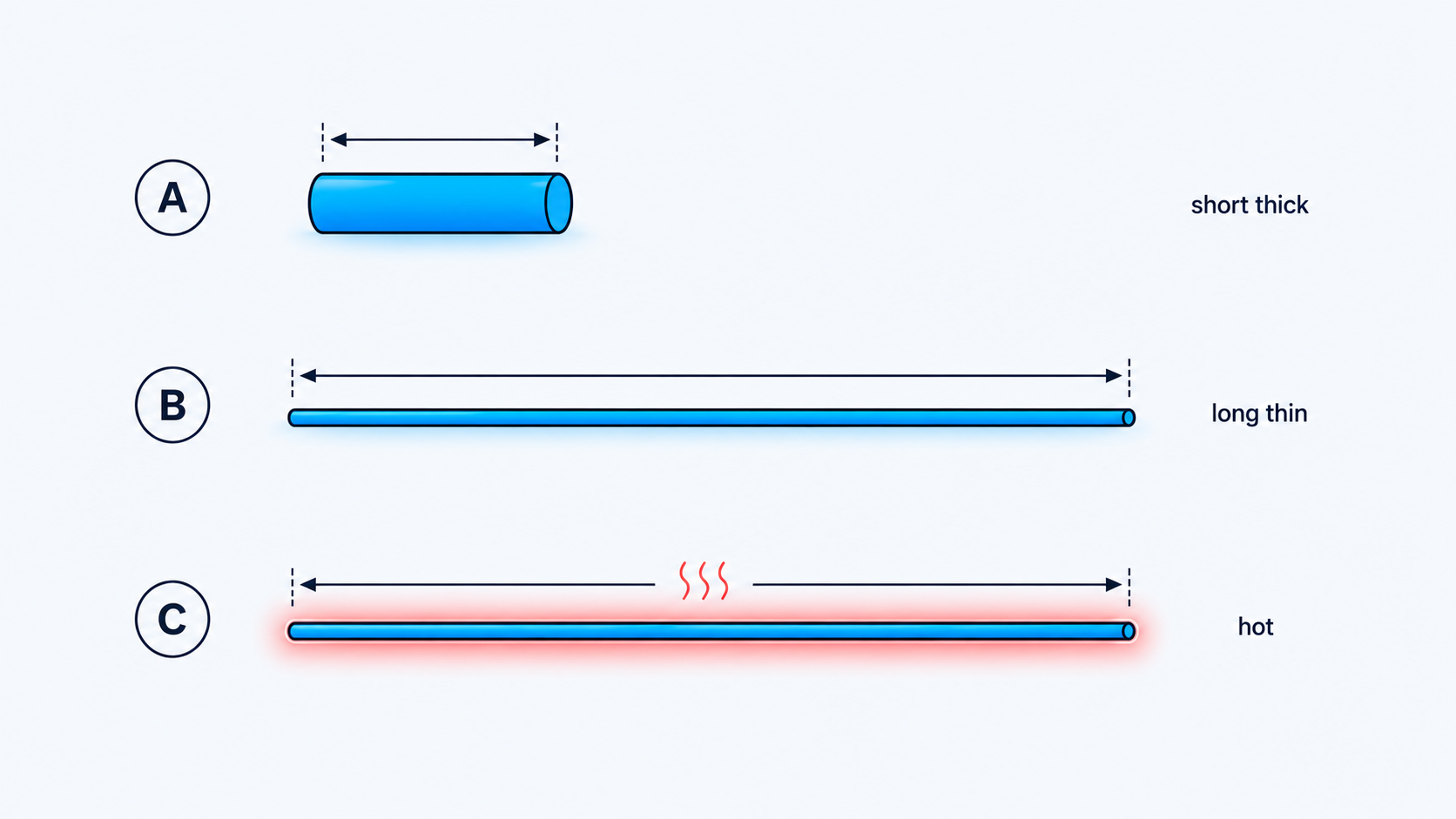
Short and thick resists little; long and thin resists a lot; and heat pushes resistance higher still. Material and geometry together set R.
Temperature raises it#
One more wrinkle: for metals, resistance climbs with temperature. Hotter lattice, bigger atomic vibrations, more collisions. The relationship is linear over normal ranges:
R(T) = R₀ · [1 + α·(T − T₀)]where α is the material’s temperature coefficient (for copper, about 0.0039 per °C). Our 0.17 Ω wire, heated from 20 °C to 100 °C:
R = 0.17 × [1 + 0.0039 × (100 − 20)] = 0.17 × 1.312 ≈ 0.22 ΩA 31% rise. Usually a nuisance, occasionally a feature (it’s how some thermometers work), and the reason an incandescent bulb’s cold filament measures roughly a tenth of its glowing, operating resistance. The inrush when you flip the switch is exactly why old bulbs so often died at the moment you turned them on.
Note
The reciprocal of resistance gets its own name: conductance, G = 1/R, measured in siemens (S). A 10 Ω resistor has a conductance of 0.1 S. It sounds redundant now, but in Part 3 you’ll see parallel circuits where conductances simply add, and suddenly it’s the convenient way to think.
Ohm’s Law: the workhorse#
Now the law that ties Parts 1 and 2 together. In the 1820s, Georg Ohm measured how current through a conductor responds to the voltage across it, and found the relationship electronics has leaned on ever since. For a resistor, voltage, current, and resistance lock together:
V = I · R I = V / R R = V / IOne law, three rearrangements, three jobs:
- V = I·R predicts the voltage that appears across a resistance carrying a known current.
- I = V/R predicts the current that a known voltage will push through a resistance.
- R = V/I lets you measure an unknown resistance from a voltage and a current reading.
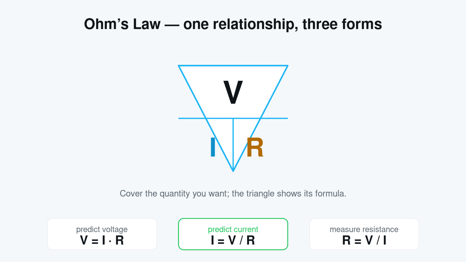
The classic memory aid: cover the quantity you want, and the triangle shows the formula. Three faces of one law.
Worked example (predict). Put 9 V across a 330 Ω resistor. How much current flows?
I = V / R = 9 / 330 = 0.0273 A = 27.3 mAThat’s it. No calculus, no mystery; a battery, a resistor, and one division. It’s hard to overstate how much of practical electronics is exactly this calculation repeated in different costumes.
Tip
Keep the units straight and Ohm’s Law never lies: volts, amps, and ohms. If your current comes out in milliamps (mA), that’s thousandths of an amp; 0.0273 A = 27.3 mA. The metric prefixes from Part 1’s toolkit (milli, micro, kilo, mega) do heavy lifting here.
The “hello world” of electronics#
Now the design direction, the one that makes this feel like a superpower. You have a light-emitting diode (LED) that wants 2 V across it and 20 mA through it to shine happily, and a 9 V battery. Connect the LED straight to the battery and it dies instantly: 9 V is more than four times the push it can handle.
The fix is a resistor in series, whose job is to soak up the leftover voltage. The battery provides 9 V; the LED takes its 2 V; the resistor must drop the remaining 9 − 2 = 7 V, while passing the desired 20 mA. Which resistor does that? Ohm’s Law, third form:
R = V / I = 7 / 0.020 = 350 Ω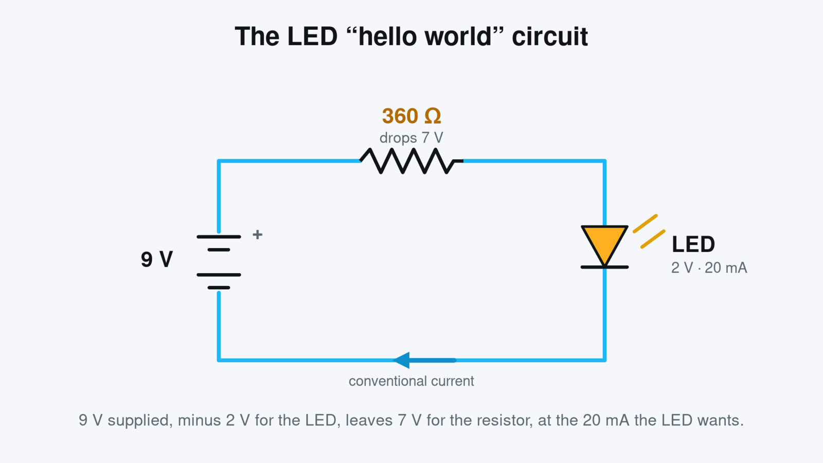
The first circuit everyone builds: battery, resistor, LED. The resistor drops the 7 volts the LED can’t handle, at exactly the current it wants.
You won’t find a 350 Ω resistor in any parts drawer, though, for reasons we’ll get to below; the nearest standard value is 360 Ω. Does the substitution hurt? Check it with the second form of the law:
I = V / R = 7 / 360 = 0.0194 A ≈ 19.4 mA19.4 instead of 20: the LED shines imperceptibly dimmer and lives a long, safe life. Congratulations, you’ve just designed something. That little calculation, wanting a current, and choosing a resistance to get it, is the seed of every circuit you’ll ever build.
What the V–I line tells you#
There’s a picture hiding in Ohm’s Law worth pulling out. Plot current against voltage for a resistor and you get a straight line through the origin, with slope 1/R. Double the voltage, double the current; the ratio never changes. Components that behave this way are called ohmic, and the resistor is the flagship.
Not everything is so obedient. A diode barely conducts and then suddenly floods; a bulb’s filament changes resistance as it heats. Their V–I plots curve, and we call them non-ohmic. That’s not a failure of Ohm’s Law; V = I·R still tells you the resistance at any single operating point. It just means R itself isn’t constant for those devices.
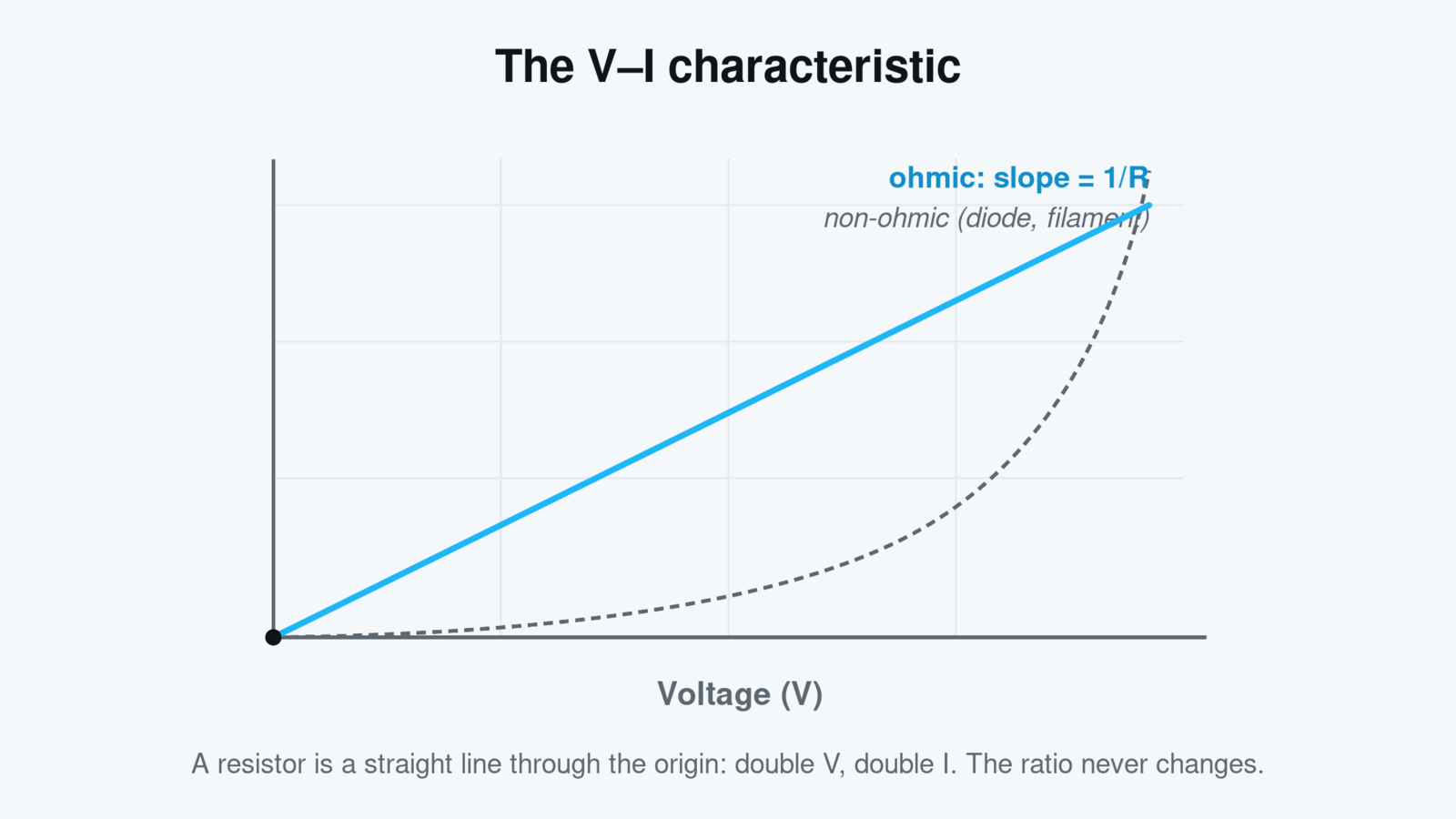
An ohmic device plots as a straight line whose slope is 1/R. Curves mean the resistance changes with operating conditions: the signature of diodes, filaments, and other non-ohmic parts.
Important
Ohm’s Law applies between any two points of a circuit, using the voltage across that piece and the resistance of that piece. The most common beginner error is mixing quantities from different parts of the circuit, like dividing the battery’s full 9 V by the LED resistor’s 360 Ω while forgetting the LED’s 2 V share. Always ask: voltage across what, current through what?
The bird on the wire, solved#
Part 1 owed you an explanation: why can a bird perch on a bare power line carrying a monstrous current and feel nothing? Now we have the tools to actually compute it.
Current flows through the bird only if there’s a voltage difference between its feet, and Ohm’s Law tells us what that difference is: V = I·R, where R is the resistance of the few centimeters of wire between the feet. Power lines are fat aluminum, engineered for minimal resistance. Take a realistic line with a 500 mm² cross-section (ρ for aluminum ≈ 2.8 × 10⁻⁸ Ω·m) and a bird standing on 5 cm of it:
R = ρL/A = (2.8×10⁻⁸ × 0.05) / (5×10⁻⁴) = 2.8×10⁻⁶ Ω  (2.8 µΩ)
V = I·R = 100 A × 2.8×10⁻⁶ Ω = 0.00028 V  (0.28 mV)
A hundred amps roar past underneath, and the push available to drive current through the bird’s body is a third of a millivolt. Effectively nothing. The bird is fine, not because current is harmless, but because voltage between its feet is microscopic.
Warning
The same physics explains why touching a line and anything else (a pole, another line, the ground) is lethal: now the two contact points sit at wildly different voltages, and your body becomes the resistor in V = I·R. Respect for high voltage is just Ohm’s Law taken seriously.
Real resistors: reading the stripes#
Time to meet the physical component. A resistor is the humblest part in electronics: two wires and a lump of resistive material, made deliberately to have a specific R. Its two headline specs are its resistance value and its power rating, the wattage it can dissipate without cooking (that one stars in Part 3).
The value is usually painted on as a color code. The common 4-band scheme: the first two bands are significant digits, the third is a multiplier (a power of ten), and the fourth is the tolerance.
Value = (digit₁ digit₂) × 10^multiplier   ± tolerance
Example: brown–black–red–gold → 1, 0 × 10² = 1000 Ω = 1 kΩ, ±5%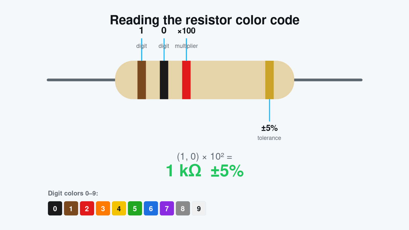
Two digits, a multiplier, a tolerance: four stripes encode the value. Brown-black-red-gold is 1 kΩ at ±5%.
And here’s the answer to the 350 Ω mystery. Because every resistor has a tolerance (±5% is typical), it would be pointless to manufacture values closer together than the tolerance can distinguish. So the industry standardized on the E-series: E12 gives twelve values per decade (10, 12, 15, 18, 22, 27, 33, 39, 47, 56, 68, 82, then ×10, ×100…), E24 doubles that. That’s why your parts drawer has 330 Ω and 360 Ω but no 350 Ω, and why engineers develop a strange affection for numbers like 47 and 68.
Putting it together#
The control knob, assembled:
- Resistance (R, ohms) is opposition to current: carriers colliding with the lattice, shedding energy as heat. It’s set by material and geometry, R = ρL/A, and for metals it rises with temperature.
- Conductance (G = 1/R, siemens) is the same fact viewed from the other side, and it will earn its keep in parallel circuits.
- Ohm’s Law, V = I·R, is one relationship read three ways: predict a voltage, predict a current, or measure a resistance. On a V–I plot, ohmic devices are straight lines with slope 1/R.
- Real resistors announce their value in color bands and come in E-series standard values, with a tolerance that explains why the series is coarse.
And the water picture is now complete: pressure (voltage), flow (current), water (charge), and pipe narrowness (resistance), all bound by one law.
But something has been quietly nagging at the edges of this whole article. Resistors turn electrical energy into heat: the wire warms, the filament glows, the LED resistor soaks up 7 volts’ worth of energy every second. How much energy is that? How much heat can a small part survive? And what happens when circuits stop being one battery and one resistor, and become networks with branches and loops?
That’s power, energy, and the circuit laws: Kirchhoff, series, parallel, and the tricks that tame real schematics. All of it in Part 3.
See you there.
This is Part 2 of the LearningBot series Current Thinking: The Foundations of Electricity & Electronics. Previously: Part 1: What Electricity Actually Is: Charge, Current, and Voltage. Next up: Part 3: Power, Energy & Circuit Laws: How Real Circuits Behave.